Lab 1 - GNS3 Setup
Overview
In this lab, you will install and configure GNS3 on your computer and setup your first network topology.
What is GNS3?
GNS3 is used by network engineers to emulate, configure, test and troubleshoot virtual and real networks. GNS3 allows you to run a small topology consisting of only a few devices on your laptop, to those that have many devices hosted on multiple servers or even hosted in the cloud. -- https://docs.gns3.com/docs/
For your reference, detailed installation document for all platforms is available on the GNS3 website, as the process does vary somewhat between platforms:
- Windows: https://docs.gns3.com/docs/getting-started/installation/windows
- Mac: https://docs.gns3.com/docs/getting-started/installation/mac
- Linux: https://docs.gns3.com/docs/getting-started/installation/linux
Step 1 : Install VMware
Install VMware Fusion (Mac) or VMware Workstation (Windows). Normally these are paid ($$) commercial products, but SOECS has free licenses for Pacific students.
Do not use the stripped-down free VMware Player. It does not come with support for the VIX API, which allows programs (like the GNS3 network simulator) to control the operation of virtual machines.
VirtualBox is supported by GNS3. (But the instructor has not tested it.)
Step 2: Install GNS3
Note: Install GNS3 inside your native operating system. Do not put it inside your Ubuntu VM or you'll run into an eventual issue with nested virtual machines. We'll use Ubuntu for class projects and homework assignments.
- Go to https://www.gns3.com/
- Select “Free Download"
- Select Windows, Mac, or Linux as appropriate, and then “Download"
- Create your GNS3 Community Account as prompted, login, and then return to the Download page
- Run the installer you downloaded and accept the default options. (If prompted, permit ubridge to run as root to capture packets)
Step 3: Install GNS3 VM
After installing the base GNS3 program, you next need to install the “GNS3 VM”. It’s a Ubuntu Linux virtual machine that has all the necessary software pre-installed that allows you to simulate more complicated devices. This is why VMware was needed as the first installation step - it will be doing some of the virtualization heavy lifting.
- Go to https://www.gns3.com/software/download-vm
- Select the image for “VMware Workstation and Fusion"
- Extract the .zip file
- Launch VMware (Fusion or Workstation)
- Select “Import” (or “Open a Virtual Machine”) and navigate to the .ovf file ("GNS3 VM.ovf") that you just downloaded and unzipped
- Let VMware import it as a new VM. Accept the default location and accept the default name it offers ("GNS3 VM") since that will simplify locating it later.
Step 4: GNS3 Setup
- Launch GNS3
- Mac: You will see the prompt “uBridge requires root permissions to interact with network interfaces”. Say YES, that will allow us to connect GNS3 with the real network if we desire.
- Next, choose how to run your GNS3 network simulations. Your choices are:
- Run appliances on my local computer
- Run appliances in a virtual machine <- Choose this option
- Run appliances on a remote server
- Next, enter the GNS3 local server settings
- The default server path, binding, and port are fine here
- Next, enter the “GNS 3 VM” settings
- If you correctly installed the GNS3 VM above (downloaded it, imported it into VMware, and accepted the default name of “GNS 3”), it should be auto-detected now. One CPU core and 2048MB of RAM should be sufficient to accommodate all the virtual routers we might want to simulate at any given time. Hopefully.
- VMware should be automatically launched now, and start running the GNS 3 VM by itself. This is thanks to the VIX API that allows GNS3 to control VMware.
- Complete the setup wizard. Note: You can change these settings at any time by locating the “Setup Wizard” from the application menus.
Step 5: Install Mikrotik Router into GNS3
Out of the box, GNS3 doesn’t come with any routers, just a very basic switch, hub, and a stripped down “computer” suitable for basic network connectivity tests. That’s about it. However, by integrating with some emulator software (QEMU) and a x86/x64 virtualization engine (VMware), it has the capability to run real operating systems for routers. As in, you can give GNS3 the same binary image you'd load on the real router, and (with proper configuration...) it will "just work". So, rather than working with a facsimile of a router, you can interact with the real router software.
Let's configure GNS3 with the image of a real router from MikroTik, which is the same vendor as the routers that are in the networking lab in CTC 214. As a bonus, unlike certain other vendors (cough Cisco cough), their OS images are freely available and easy to download.
First, obtain the router OS image:
- Go to https://mikrotik.com/
- Click on “Software"
- Scroll down to their “Cloud Hosted Router” section. That’s just their marketing term for a software router (Linux + their proprietary command line interface) that could run on any old PC that has a couple of network cards in it.
- Look at the column labeled “Stable”, and go down to the row labeled “Raw disk image”. That’s the download link you want.
- For example, in August 2020 the latest stable release was 6.47.1, and the download link for the raw disk image was https://download.mikrotik.com/routeros/6.47.1/chr-6.47.1.img.zip
- Unzip the file
Next, configure GS3 to recognize this image as a valid router, suitable for placement into a network diagram:
- In GNS3, go to the Preferences window
- Locate the QEMU section in the panel window, and under it, the section labeled “Qemu VMs"
- Select “New” to create a new Qemu VM template
- Select “Run this Qemu VM on the GNS3 VM"
- Enter a name for your image - “Mikrotik 6.47.1” is a helpful and obvious name - and click Next
- Select the amount of RAM for your router OS - 256MB is sufficient here, and given that we will eventually want multiple routers, it’s best not to pick too large of a number
- Choose your console type - “Telnet” - and click Finish
- Choose your disk image, which is the .img file you downloaded previously. Allow GNS3 to copy it to the default images directory, and click Next.
- Your template is now created, but there’s a few subtle but important network settings to change. Locate the “Network” panel for the Mikrotik image you created.
- Currently it says 1 adapter (Ethernet) of type e1000. Change it to have 4 adaptors. No point in having a router with a single network interface! Click “Edit", select the “Network” tab, and change the 1 to a 4.
- Change the Name format from “Ethernet” to “Ether” to match the router CLI syntax.
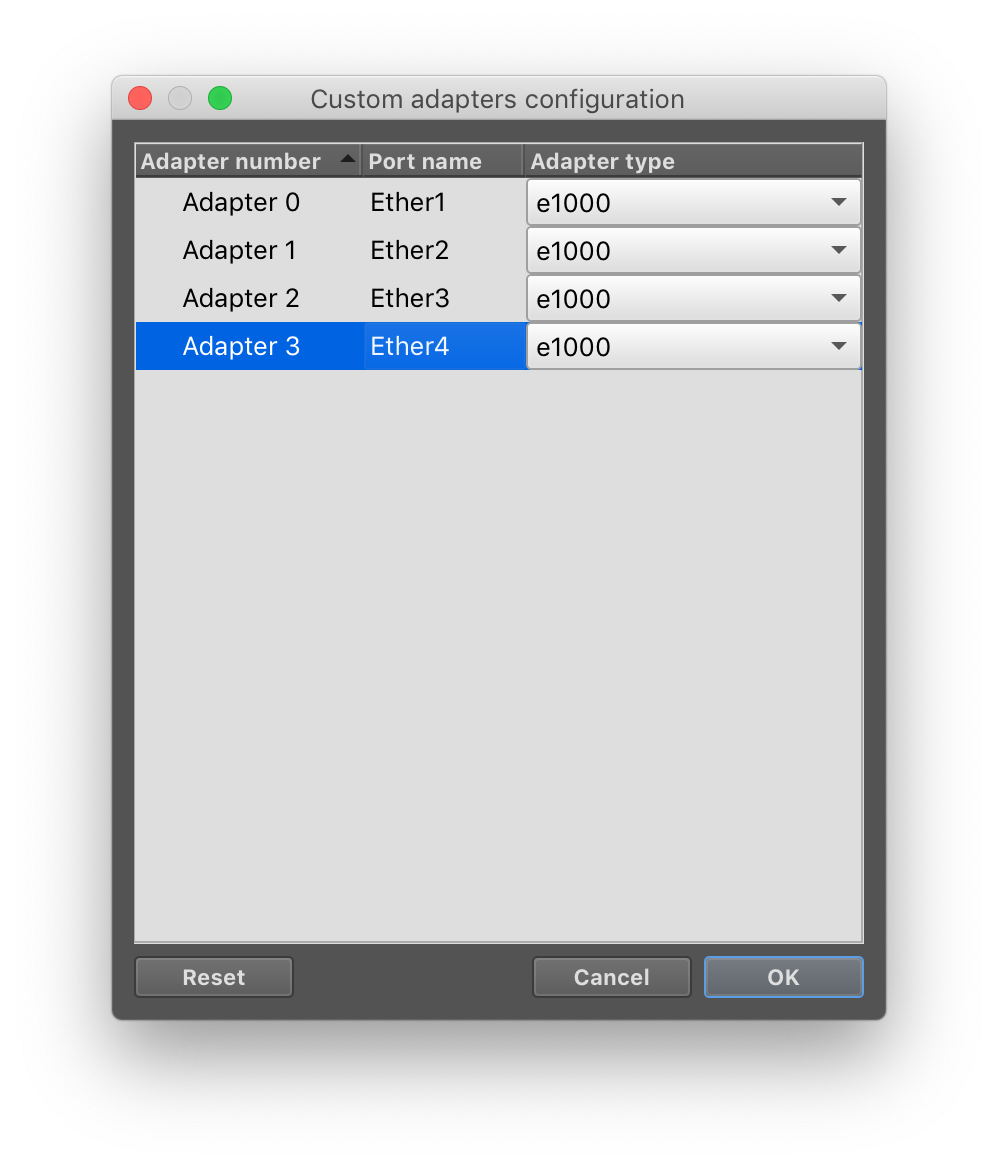
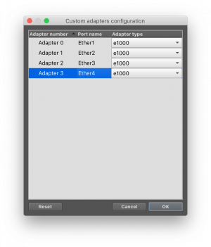 Finally, fix an annoying display issue. GNS3 numbers its ports starting from 0, but Mikrotik numbers its ports starting at 1. You can anticipate the frustration if you mix this up in a lab and network data is going out across the wrong wire to the wrong destination. To fix this, click on the “Configure custom adapters” button and re-name the Port names from
 Ethernet0,...,Ethernet3toEther1,..,Ether4. That will match the Mikrotik labels in the OS.
- Under the “General Settings” panel, change the “Category” from “End Devices” to “Routers" so this device is in the router category.
- Under the "General Settings" panel, change the "Symbol" that appears in the network diagrams. Click on Browse, and under "Classic", find the icon for the "Router".
- Under the "General Settings" panel, change the "On Close" option from "Power Off" (Harsh! Abrupt! Router OS will complain!) to "Send the Shutdown Signal (ACPI)" which is gentle and orderly.
- Select “Ok” to edit the Preferences panel entirely.
Behind the scenes, GNS3 will copy the disk image for the Mikrotik router into the GNS VM (in VMware) that you installed previously. That VM contains all the necessary software and settings to virtualize this router.
Now you have a router that can be added to your network!
Step 6: First Network
- Create a “New Blank Project” and call it
lab01. - Drag two “VPCS” (Virtual PCs) onto the blank network diagram from the panel at left (found under the “Browse End Devices” button)
 . If prompted to "Choose a server", select "GNS3 VM".
 - Drag a “Mikrotik 6.x” router onto the network diagram from the panel at left (found under the “Browse Routers” button)

- Using the “Add a link” button
 on the left panel, wire up the network using virtual Ethernet cables! Make your network look like the network below.
- Note: The PCs only have 1 interface, so you can’t connect the wire to the wrong port there
- Note: The Router has 4 interfaces. The ports you plug your network wires into must be consistent with the way you configure your router in software. For now, just carefully match the diagram. In future labs, when you’re more comfortable, you can make port decisions on your own.
- Note: Wondering why your diagram doesn’t show port labels? Press the “Show/Hide Interface Labels” button.

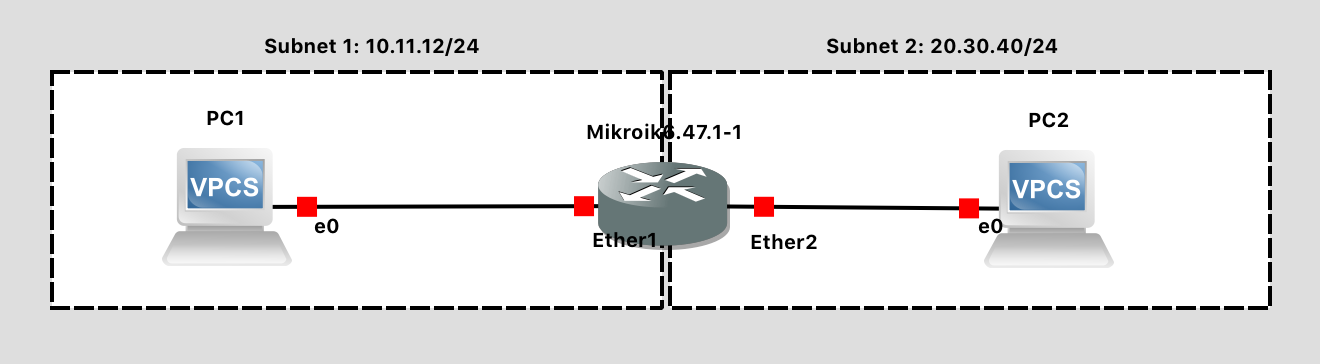
Lab 1 Network Diagram (Note: Subnet labels and dashed borders are for informational use only)
- Press the Start button
 to launch your two virtual PCs and router. All the links should turn from RED to GREEN.
 - Press the Console Connect to All Nodes button
 to pull up a terminal to all three devices. (You could right-click on each and choose Console as well, but we need to configure all three).
At the MikroTIk console:
- Note: We are configuring the router first, because we can’t configure the PC network fully until the default gateway (the router) exists.
- Enter the default Mikrotik login of
adminwith a blank password. - Select N when prompted to view the license file.
- Configure two interfaces (corresponding to the two wires plugged in)
ip address add address=10.11.12.254/24 interface=ether1ip address add address=20.30.40.254/24 interface=ether2
- Print the configuration to confirm:
ip address print
At the PC1 console:
- Show the help menu for available command (recall that this is a rudimentary simulated PC):
help - Configure an IP address:
ip 10.11.12.1/24 10.11.12.254- This sets up a subnet of 10.11.12/24, assigns the PC the IP address 10.11.12.1, with a default gateway of 10.11.12.254 (which is the router)
- Show the configuration:
show ip - Save the configuration to persist after power cycling:
save
At the PC2 console:
- Configure an IP address:
ip 20.30.40.1/24 20.30.40.254- This sets up a subnet of 20.30.40/24, assigns the PC the IP address 20.30.40.1, with a default gateway of 20.30.40.254 (which is the router)
- Show the configuration:
show ip - Save the configuration to persist after power cycling:
save
Finally, demonstrate the network is functional:
- Go to the PC 1 console
- Ping PC2 through the router:
ping 20.30.40.1 - You should see something to the effect of
84 bytes from 20.30.40.1 icmp_seq=1 ttl=63 time=2.699 msindicating that PC2 is responding to PC1. - Press CTRL-C to exit
Lab Submission Instructions:
Take a screenshot showing:
- Your GNS3 topology
- Your PC1 terminal with BOTH its IP address information AND the successful ping(s) to PC2 clearly visible.
Upload your screenshot to the Lab 1 Canvas assignment.
When finished, press the Stop button  and exit GNS3. The GNS3 VM (in VMware) should halt and exit automatically.
GNS3 Operation
Troubleshooting Tips
For all errors of the type "Cannot connect to compute 'GNS3 VM' with request..."
- Look in VMware to see the "blue splash screen" where your GNS3 VM is running. It will say: "To launch the Web-Ui: http://aaa.bbb.ccc.ddd" - Can you load that up in your web browser to verify networking with the VM is functional? That address will take you to the alternate web interface for GNS3, which runs out of the VM.
- Under GNS3 -> Preferences -> GNS3 VM - Ensure that the port is set to 80. (This should be the same port number you see in VMware when the GNS3 VM is running)
- For VMware Workstation Pro (on Windows): Try resetting your virtual network adaptors. Stop the GNS3 VM, and then go to Edit->Virtual Network Settings. Click "Change Settings" and then "Restore Defaults". Exit VMware, exit GNS3, and then try again. This may be a temporary (but simple) fix.
- For VMware Workstation Pro (on Windows): Try disabling and enabling any "VMnet" virtual network adaptors. Go to Control Panels -> Network & Internet -> Network & Sharing Center -> Change Adapter Settings. Find any that are "VMnet" and disable/enable them.
- For VMware Workstation Pro (on Windows): Under the Edit->Virtual Network Settings, try changing your VMnet8 (or equivalent) adaptor so that it is bridged with the specific network interface you are using to access the Internet, instead of auto-detected (which may be going awry). This may be a longer-term fix, if successful.
Upgrading
The GNS3 GUI client can be updated at any time. It will automatically check for updates and prompt you.
After the GNS3 client is updated, the GNS3 VM (in VMware) also needs to be updated. Find the virtual machine console - it should automatically start when the client is started. Press ENTER (OK) to go into the main menu, and then using the arrow keys, select the "Upgrade" option to Upgrade the GNS3 VM. Confirm that you want to upgrade, and select the most recent GNS3 version offered. This should be consistent with the version of the GUI client you just downloaded and installed. The update system will now download and install the latest VM release, after which the VM will restart.