Lab 10 - GRE and OSPF
In this lab, you'll use a GRE tunnel and OSPF routing to connect a "remote" business office to a "headquarters" business network.
Design Network
Your network topology should match this design. As was done in a previous lab, the "DHCPServer" is really a Mikrotik router, but one that is configured as an endpoint instead of a router.
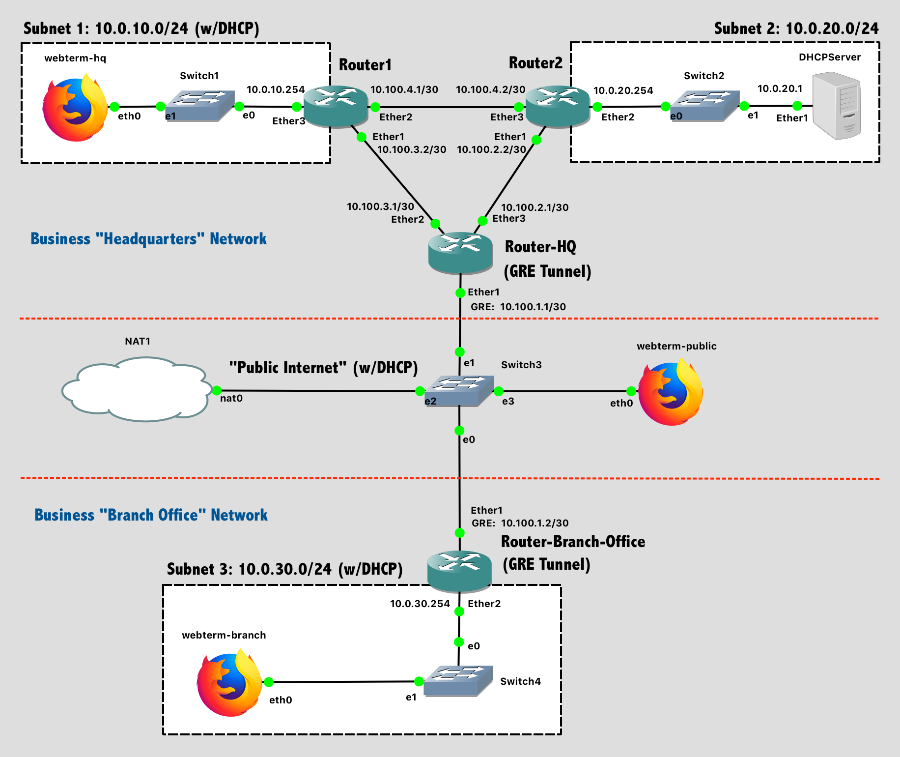
Lab 10 Network Diagram (Note: Subnet labels and dashed borders are for informational use only)
Implementation
Pre-Configuration Steps
- Configure the hostnames of the routers (and the DHCPServer "router") in GNS3 to prevent confusion (via the GUI).
- Configure the hostnames of the routers in the router itself to prevent confusion (via the CLI).
- Configure the DHCP client on all the Webterm clients
- Disable the DHCP client on DHCPServer - it's not needed.
- Configure DNS for Router-HQ, Router-Branch-Office, Router1, Router2, and DHCPServer using the Google Public DNS IP addresses:
ip dns set servers=8.8.8.8,8.8.4.4followed byip dns printto confirm your setup.
Configure "Public Internet"
The "public Internet" portion of this network has Internet access via a NAT node. To configure this portion of the network:
- Configure the DHCP Client on
Router-Branch-OfficeandRouter-HQto run on theether1interface. They will obtain an IP address from the NAT node. - Configure the DHCP Client on
webterm-public. It will obtain a network address from the NAT node.
After configuring, test that Router-Branch-Office and Router-HQ can both ping google.com, and ensure that webterm-public can access the Internet, load web pages, etc.
Configure GRE Tunnel with IPSec Encryption
Using Generic Routing Encapsulation (GRE) with IPSec, create an encrypted tunnel between the "remote" business network and the "headquarters" business network.
First, find the IP addresses of Router-Branch-Office and Router-HQ that were obtained via DHCP: ip address print. While these are technically still private addresses (due to the NAT), we'll act as though this is the public Internet.
Next, using these "public" IPs, configure virtual network adaptors on both routers to create the tunnel endpoints. Hardware-accelerated routing (the "fast path") needs to be disabled, as it is not supported on this software router:
- On Router-Branch-Office:
interface gre add name=gre-tunnel remote-address=IP-OF-ROUTER-HQ local-address=IP-OF-ROUTER-BRANCH-OFFICE ipsec-secret="SecretTigerPassword" allow-fast-path=no - On Router-HQ:
interface gre add name=gre-tunnel remote-address=IP-OF-ROUTER-BRANCH-OFFICE local-address=IP-OF-ROUTER-HQ ipsec-secret="SecretTigerPassword" allow-fast-path=no
Assign IP addresses to these virtual network adaptors so that they can be used in the network.
- On Router-Branch-Office:
ip address add address=10.100.1.2/30 interface=gre-tunnel - On Router-HQ:
ip address add address=10.100.1.1/30 interface=gre-tunnel
Provide a screenshot verifying that your GRE tunnel is operational. From Router-HQ, ping the tunnel IP of Router-Branch-Office: 10.100.1.2. This will go through the tunnel.
Configure HQ Network Routing with OSPF
In the headquarters network, the Open Shortest Path First (OSPF) protocol will be used instead of RIP to dynamically generate routing table entries. To enable OSPF on Router1, Router2, and Router-HQ, use the following steps.
First, configure all static IP addresses on the three routers.
Second, verify that an OSPF instance called default already exists: routing ospf instance print
Third, verify that the default OSPF area called backbone already exists: routing ospf area print
Fourth, on each router, add the networks that are directly connected to it via routing ospf network add network=aa.bb.cc.dd/n area=backbone. Do NOT include the "public Internet" here.
- Router-HQ sees the local networks
10.100.3.0/30and10.100.2.0/30 - Router1 sees the local networks
10.100.3.0/30,10.100.4.0/30, and10.0.10.0/24 - Router2 sees the local networks
10.100.4.0/30,10.100.2.0/30, and10.0.20.0/24
To verify that OSPF is functional:
- Verify that each OSPF-enabled router sees its neighbors:
routing ospf neighbor print - Verify that each routing table is valid and contains routes to distant subnets that you would expect to see:
ip route print- Note that Router-HQ, by virtual of being connected to the "Internet" as well as the GRE tunnel, will have additional routes compared to Router1 and Router2, which will only see directly-connected networks as well as routes advertised through OSPF.
- From Router-HQ, ping the distant ports of Router1 and Router2:
10.0.10.254and10.0.20.254. These IPs are in distant subnets that are only visible to Router-HQ if OSPF is functional.
Note that, while Router-HQ has a default route (0.0.0.0/0) and thus can ping 8.8.8.8 directly (try it!), the same cannot be said for Router1 and Router2 (try it, you'll get a no route to host error. ). Unless otherwise specified, OSPF will not distribute the default route (that Router-HQ has) to other routers in the area. Thus, Router1 and Router2 do not know how to get to arbitrary subnets, only to the specific subnets that OSPF advertised.
To enable default route distribution, so that all routers (and devices) can have Internet access, enable it on RouterHQ:
# Observe the number for the "default" instance
routing ospf instance print

# Change the setting
routing ospf instance set distribute-default=always-as-type-1 numbers=0

# Verify it was changed
routing ospf instance print
Now Router1 and Router2 should see a default route. Try pinging 8.8.8.8 again - the no route to host error is gone! But, the ping times out. You could run Wireshark on various links to see your ping heading to the Internet and replies returning, and diagnose the problem. The issue is a lack of network address translation (NAT) on Router-HQ - the outgoing ping is going to the NAT node, but the simplistic GNS3 NAT node doesn't know how to translate the response into the rest of the virual network.
Enable NAT on Router-HQ so that all internal corporate devices appear to come from that router: ip firewall nat add chain=srcnat action=masquerade out-interface=ether1. After that, your pings should succeed.
Provide a screenshot showing that Router1 and Router2 can both ping google.com.
Configure Branch Office Network with OSPF
In the branch office, the Open Shortest Path First (OSPF) protocol will also be used. Here, however, it will be configured to extend the "headquarters" network over the GRE Tunnel to the brach office, all while appearing as encrypted data on the public Internet.
First, configure all static IP addresses on Router-Branch-Office.
Second, verify that an OSPF instance called default already exists: routing ospf instance print
Third, verify that the default OSPF area called backbone already exists: routing ospf area print
Fourth, on Router-Branch-Office, add the networks that are directly connected to it via routing ospf network add network=aa.bb.cc.dd/n area=backbone. Do NOT include the public Internet here.
- Router-Branch-Office sees
10.0.30.0/24and10.100.1.0/30(the GRE tunnel)
Finally, to mirror that last step, on Router-HQ, add the same GRE tunnel network (10.100.1.0/30) as an OSPF network.
To verify that OSPF is functional:
- Verify that Router-Branch-Office sees its neighbor (Router-HQ) over OSPF via the
gre-tunnelinterface:routing ospf neighbor print - Verify that the routing table is valid and contains routes to distant subnets that you would expect to see:
ip route print. The next-hop for these routes should be the tunnel IP of Router-HQ. In other words, to reach all the subnets at corporate HQ, traffic should go through the GRE tunnel to Router-HQ.
Provide a screenshot showing that Router-Branch-Office can ping the distant ports of Router1 and Router2: 10.0.10.254 and 10.0.20.254
Provide a screenshot of ip route print on Router-Branch-Office showing routes that go through the GRE tunnel.
Similar to the HQ network, the branch office network also has a default route to the Internet, and also needs NAT enabled on Router-Branch-Office: ip firewall nat add chain=srcnat action=masquerade out-interface=ether1.
Configure DHCPServer for Network
A single centralized DHCPServer is present on the corporate network. Devices in Subnet 1 (10.0.10.0/24) and Subnet 3 (10.0.30.0/24) should be able to obtain addresses via DHCP relay from the centralized DHCPServer. As was done in a previous lab, this "DHCPServer" is really a Mikrotik router that is acting as a DHCP server instead of a router. Be sure to manually give it a default route to Router2. Before troubleshooting DHCP itself, ensure that DHCPServer can successfully ping Router2, Router1, Router-HQ, and Router-Branch-Office.
Provide a screenshot of ip dhcp-server lease print on DHCPServer showing the two expected leases.
Provide a screenshot showing that webterm-branch can ping webterm-hq, thus demonstrating that the devices have IP addresses from DHCP and that routing is functional.
Provide a screenshot showing that both webterm-branch and webterm-hq can ping google.com
Firewalls
Deploy a network firewall on both Router-Branch-Office and Router-HQ for security purposes.
Inbound traffic (where the destination IS the router) should only be allowed if:
- It is IP protocol 50 (ESP - Encapsulating Security Payload, i.e. the encrypted tunnel):
ip firewall filter add chain=input action=accept protocol=50 connection-state=new comment="Permit IP protocol 50 - ESP" - It is UDP destination port 500 (ISAKMP - Internet Security Association and Key Management Protocol, i.e. configuring keys for the encrypted tunnel):
ip firewall filter add chain=input action=accept protocol=udp dst-port=500 connection-state=new comment="Permit ISAKMP" - It comes from the corporate network:
ip firewall filter add chain=input action=accept src-address=10.0.0.0/8 connection-state=new comment="Permit local" - It is part of an existing connection:
ip firewall filter add chain=input action=accept connection-state=established,related comment="Accept established connections" - Everything else should be denied:
ip firewall filter add chain=input action=drop comment="Default deny"
After adding the firewall rules, confirm that you can still ping Internet destinations and still ping across the GRE tunnel between the branch network and HQ network.
Provide a screenshot of ip firewall filter print on Router-HQ and Router-Branch-Office showing the implemented rules.
Lab Submission
Submit the following items to the Lab 10 Canvas assignment:
- Provide a screenshot showing your GNS3 topology
- Provide a screenshot verifying that your GRE tunnel is operational. From Router-HQ, ping the tunnel IP of Router-Branch-Office:
10.100.1.2. This will go through the tunnel. - Provide a screenshot showing that
Router1andRouter2can both pinggoogle.com. - Provide a screenshot showing that Router-Branch-Office can ping the distant ports of Router1 and Router2:
10.0.10.254and10.0.20.254 - Provide a screenshot of
ip route printon Router-Branch-Office showing routes that go through the GRE tunnel. - Provide a screenshot of
ip dhcp-server lease printon DHCPServer showing the two expected leases. - Provide a screenshot showing that
webterm-branchcan pingwebterm-hq, thus demonstrating that the devices have IP addresses from DHCP and that routing is functional. - Provide a screenshot showing that both
webterm-branchandwebterm-hqcan pinggoogle.com - Provide a screenshot of
ip firewall filter printon Router-HQ and Router-Branch-Office showing the implemented rules. - Provide short answers to the following questions. Use
tracerouteon the webterms to verify your answers.- What hops does a packet from
webterm-branchtowebterm-hqtake? - What hops does a packet from
webterm-branchtogoogle.comtake? (You only need to provide the hops within your simulated network) - What hops does a packet from
webterm-hqtogoogle.comtake? (You only need to provide the hops within your simulated network)
- What hops does a packet from
When finished, press the Stop button and exit GNS3. The GNS3 VM (in VMware) should halt and exit automatically.