Lab 12 - OpenFlow
In this lab, you'll configure a routed network that uses Software-Defined Networking (SDN) over OpenFlow Layer 3 switches.
Software Defined Networking
What is SDN and OpenFlow?
Design Network
Your final network topology should match this design.
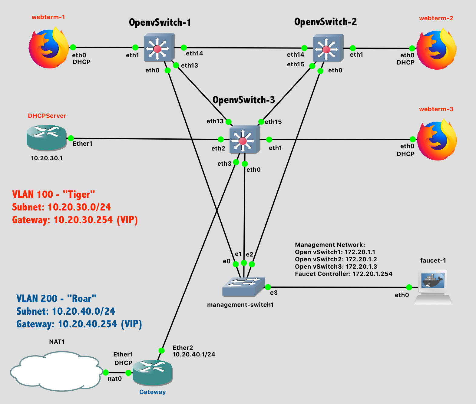
Lab 12 Network Diagram - Stage 3 (Note: Subnet labels and dashed borders are for informational use only)
References:
- GNS3 - SDN Lab with Faucet controller and OpenvSwitch
- Installing Faucet for the first time
- Installing Faucet with Docker
- Using OpenFlow FAQ
- Open vSwitch Faucet Tutorial
GNS3 Configuration
Install Faucet SDN Controller
Faucet is an open-source controller for OpenFlow networks. From the Faucet website:
Faucet is a compact open source OpenFlow controller, which enables network operators to run their networks the same way they do server clusters. Faucet moves network control functions (like routing protocols, neighbor discovery, and switching algorithms) to vendor independent server-based software, versus traditional router or switch embedded firmware, where those functions are easy to manage, test, and extend with modern systems management best practices and tools. Faucet controls OpenFlow 1.3 hardware which delivers high forwarding performance.
https://faucet.nz/
Faucet can be installed in several methods: using pip3 (for Python), apt (from your Linux distribution package manager), or via Docker. And we're in luck - GNS3 already supports the ability to run Dockerized-applications natively in the GNS3 VM that you already have configured. We could have been running all kinds of arbitrary applications this semester, such as anything at Docker Hub.
Configure GNS3 to run Faucet as a Docker container, suitable for placement into a network diagram:
- In GNS3, go to the Preferences window
- Locate the Docker section in the panel window, and under it, the section labeled “Docker Containers". You should already see the webterm container that was previously created.
- Select “New” to create a new Docker template
- Select “Run this Docker container on the GNS3 VM"
- Select "New Image", and for the image name, enter
faucet/faucet:latest. That specifies the most recent version of the Faucet SDN Controller that can be downloaded from Docker Hub. - Enter a name for your container - “faucet” is a helpful and obvious name - and click Next
- Specify the number of network interface adaptors your container application should see. "1" is sufficient.
- Specify the start command that should be run when the container starts:
sh -c 'cd; faucet & sleep 10; ash -i -l' - Specify the console type. "Telnet" is sufficient.
- No environment variables are needed.
- Click Finish
- Your container template is now created, but there’s one more subtle but important settings to change. Click "Edit" on the template you just created.
- Under the Advanced tab, enter the path
/rootin the category "Additional directories to make persistent that are not included in the image VOLUMES config"
- Under the Advanced tab, enter the path
- Select “Ok” to edit the Preferences panel entirely.
When this container is added to a network diagram, GNS3 will download the faucet containerized application from Docker Hub and configure it according to your settings.
Install Open vSwitch (OVS)
In order for the Faucet SDN controller to have something to control, we need a new kind of network switch: A switch that supports the OpenFlow standard and allows its forwarding plane to be managed remotely over the network. Open vSwitch is a virtual switch that supports this standard.
GNS3 already has a Docker image for Open vSwitch available, and you could install it following the Docker instructions above. However, an even easier installation process is to download the the pre-packaged appliance, which will do the same installation process in fewer steps.
- Download the Open vSwitch appliance from https://www.gns3.com/marketplace/featured/open-vswitch
- In GNS3, go to File->Import Appliance
- Find the "openvswitch.gns3a" file you just downloaded
- Select "Install the appliance on the GNS3 VM"
- Select "Finish"
When this container is added to a network diagram, GNS3 will download the gns3/openvswitch:latest containerized application from Docker Hub and configure it according to your settings.
Configure Network - Stage 1
The network for Lab 12 features an "out of band" controller architecture, where the SDN controller is not part of the network being managed. (OpenFlow also supports "in band" architectures, where the controller is part of the network being managed).
For simplicity, wire up the network in three stages:
- Stage 1 - Wire up the Management Network - The
eth0interfaces from the Open vSwitch devices, through the management switch, to the Faucet SDN controller - Stage 2 - Wire up the Data Network for VLAN 100. This broadcast domain connects the webterms and DHCPServer as-if they were connected to a single switch
- Stage 3 - Wire up the Data Network for VLAN 200, the Gateway router, and the NAT interface to the public Internet.
Wire Stage 1 now - the Management network.

Lab 12 Network Diagram - Stage 1
Configure Open vSwitch
The Open vSwitch devices are essentially Linux computers with multiple network adaptors. (A commercial device might be hardware-accelerated, but this can also be done in software). Each switch needs three configuration items set:
- The management interface
eth0(connected to the management switch, and the Faucet controller) needs an IP address. - The management interface
eth0should not be a part of the software bridgebr0 - The software bridge
br0(on the switch) should be controlled by the Faucet SDN controller.
First, configure each OVS device with its own management IP address on the eth0 interface. Right-click on each device, choose "Configure" and then "Edit" under "Network Configuration". Enter the following configuration:
# Static config for eth0 - Management interface
auto eth0
iface eth0 inet static
    address 172.20.1.1
    netmask 255.255.255.0
Ensure that the three switches have management IP addresses as follows:
- OpenvSwitch-1:
172.20.1.1 - OpenvSwitch-2:
172.20.1.2 - OpenvSwitch-3:
172.20.1.3
Once the network configuration for each Open vSwitch has been set, start each device and access its console. For each switch, configure the default br0 bridge (which combines all of the physical network ports) so that it is managed by the Faucet SDN controller, and that the bridge excludes eth0 (which is being used for management and thus is considered "out of band").
$ ovs-vsctl set bridge br0 other-config:datapath-id=0000000000000001 \
            -- set bridge br0 fail_mode=secure \
            -- set-controller br0 tcp:172.20.1.254:6653 \
            -- set controller br0 connection-mode=out-of-band \
            -- --if-exists del-port eth0
Note 1: Each switch should have a datapath-id that is a unique 16 digit hex number. Setting an ID of ...00001, ...00002, ...00003 is sufficient.
Note 2: These commands could all be done separately, but there is an advantage in giving all of the commands to ovs-vsctl to be accomplished in a single transaction to avoid the network being incompletely configured between transactions.
While on each switch, take a moment to inspect the current configuration. Show information on the br0 bridge:
$ ovs-ofctl show br0On the br0 bridge, observe two things:
- The
eth0interface is not part of the bridge (because it has been specifically excluded) - The OpenFlow port numbers do not match the interface numbers. The
eth1interfce is port 2, theeth2interface is port 3, etc.. Keep this in mind! (The interfaces were numbered started at 0, but OpenFlow numbers ports starting with 1).
Show information on the controller for the br0 bridge:
$ ovs-vsctl get-controller br0
# Should see:
# tcp:172.20.1.254:6653
Show information on current flows tracked by the switch:
$ ovs-ofctl dump-flows br0
# Should see:
# NXST_FLOW reply (xid=0x4):
# (No flows, because the controller is not yet active)
Configure Faucet SDN Controller
The Faucet SDN Controller is another Linux computer running a Python application. It should also be configured to be on the management network with the unique management IP address that was already specified in the switch configuration above. Right-click on the Faucet device, choose "Configure" and then "Edit" under "Network Configuration".
# Static config for eth0 - Faucet SDN
auto eth0
iface eth0 inet static
    address 172.20.1.254
    netmask 255.255.255.0
    # Faucet needs a dummy DNS nameserver,
    # otherwise it will fail to start
    up echo nameserver 0.0.0.0 > /etc/resolv.conf
Once the network configuration for the Faucet controller has been set, start the device.
Back on a switch, check to see if there is any sign of communication with the Faucet controller:
Note: The DEMO configuration of the Faucet controller will only provide a configuration for the switches with IDs of 0x1 and 0x2. We'll fix that next by loading a full configuration, but in the meantime, the switch with ID 0x3 won't show as connected or have any flows.
$ ovs-vsctl list controller
# Example Output:  (Should see: is_connected: true  and state=ACTIVE)
# _uuid               : 88f70f02-9921-47e4-bedf-9e135e336877
# connection_mode     : out-of-band
# controller_burst_limit: []
# controller_rate_limit: []
# enable_async_messages: []
# external_ids        : {}
# inactivity_probe    : []
# is_connected        : true    **********************
# local_gateway       : []
# local_ip            : []
# local_netmask       : []
# max_backoff         : []
# other_config        : {}
# role                : other
# status              : {sec_since_connect="726", state=ACTIVE} **********************
# target              : "tcp:172.20.1.254:6653"   **********************

$ ovs-vsctl show
# Should see:   is_connected: true
# under Bridge "br0" section

$ ovs-ofctl dump-flows br0
# Switch-1 and Switch-2 should see some flows
# now from the default (DEMO) configuration
# Switch-3 has no configuration out of the box.
Configure Network - Stage 2
Wire Stage 2 of the network now - the VLAN 100 portion connecting the webterms and DHCPServer.
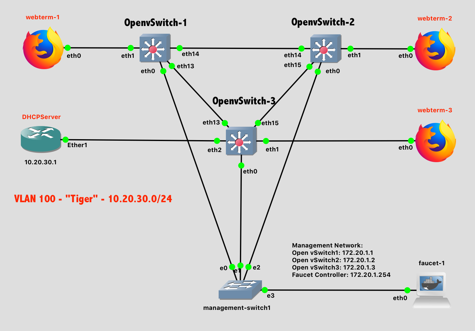
Lab 12 Network Diagram - Stage 2
Configure the webterms to obtain addresses via DHCP.
Configure DHCPServer with the address 10.20.30.1. It should provide addresses to the subnet 10.20.30.0/24 using addresses in the range 10.20.30.2-10.20.30.253 with a default gateway of 10.20.30.254 and DNS servers of 8.8.8.8 and 8.8.4.4.
Configure Faucet SDN Controller
The goal of Stage 2 is for all the webterms and DHCPServer to function as-if they were connected to the same Layer-2 (Ethernet) switch and share the same broadcast domain as part of VLAN 100. The Faucet SDN needs to be configured to make this happen. Otherwise, out of the box, each Open vSwitch is independent.
First, make a backup of the original configuration file. This is always a good practice when learning a new system:
$ cp /etc/faucet/faucet.yaml /etc/faucet/faucet.yaml.origThen, edit the Faucet network configuration to specify the desired datapath (dp). This datapath is, in essence, a single virtual switch that happens to be comprised of multiple physical switches. Each physical switch in the virtual datapath needs to specified, along with each OpenFlow port that is connected. Remember that the OpenFlow ports are numbered starting at 1, so the port number is one greater than what you see in GNS3. For ports that connect two OpenFlow switches together, the stack option is used to specify what is at the opposite end of the cable (another datapath). In this way, the entire network configuration is specified as a text file.
$ vi /etc/faucet/faucet.yaml
# Enjoy vi!   You do know how to use this classic text editor, yes?   :-)
# Tips:
#   Pressing 'd' while in command mode will delete a line
#   Pressing 'i' while in command mode will enter "Insert mode" (to edit)
#   Pressing 'ESC' while in an editing mode will switch back to command mode
#   Entering ':wq' while in command mode will write the modified file to disk and then quit
The desired contents of the YAML-formatted configuration file is:
vlans:
    tiger:
        vid: 100

dps:
    openvswitch-1:
        dp_id: 0x1
        hardware: "Open vSwitch"
        stack:
            priority: 1
        interfaces:
            2:
                name: "eth1"
                native_vlan: tiger
            14:
                name: "eth13"
                description: "Link openvswitch-1 - openvswitch-3"
                stack:
                    dp: openvswitch-3
                    port: 14
            15:
                name: "eth14"
                description: "Link openvswitch-1 openvswitch-2"
                stack:
                    dp: openvswitch-2
                    port: 15

    openvswitch-2:
        dp_id: 0x2
        hardware: "Open vSwitch"
        interfaces:
            2:
                name: "eth1"
                native_vlan: tiger
            15:
                name: "eth14"
                description: "Link openvswitch-2 - openvswitch-1"
                stack:
                    dp: openvswitch-1
                    port: 15
            16:
                name: "eth15"
                description: "Link openvswitch-2 - openvswitch-3"
                stack:
                    dp: openvswitch-3
                    port: 16

    openvswitch-3:
        dp_id: 0x3
        hardware: "Open vSwitch"
        interfaces:
            2:
                name: "eth1"
                native_vlan: tiger
            3:
                name: "eth2"
                native_vlan: tiger
            14:
                name: "eth13"
                description: "Link openvswitch-3 - openvswitch-1"
                stack:
                    dp: openvswitch-1
                    port: 14
            16:
                name: "eth15"
                description: "Link openvswitch-3 - openvswitch-1"
                stack:
                    dp: openvswitch-2
                    port: 16
Note: YAML files use spaces for indentation, not tabs
Test that your configuration file is good. Success will show a JSON-formatted output of your configuration. Failure will show an error message:
$ check_faucet_config /etc/faucet/faucet.yamlTrigger Faucet to reload and use the new configuration.
$ pkill -HUP ryu-managerVerification
Start the webterm instances and verify that they have IP addresses and can ping each other, as if they were all connected to the same switch.
- Provide a screenshot of
DHCPServershowingip dhcp-server lease printwith at least 3 current leases. - Provide a screenshot of
webterm-1successfully pingingwebterm-2andwebterm-3.
Configure Network - Stage 3
To complete the network, add in the final VLAN - VLAN 200, referred to with the label "Roar". This VLAN containers one router - Gateway - that is used to access the Internet.
Lab 12 Network Diagram - Stage 3
Add the Gateway router and configure it as follows:
- DHCP client active on the interface connected to the NAT
- IP Masquerading on the interface connected to the NAT
- Static IP address of
10.20.40.1on the interface connected to the Open vSwitch. - Static route so that the subnet
10.20.30.0/24can be reached by the gateway10.20.40.254
Ensure that the Gateway router can ping google.com before continuing.
Configure Faucet SDN Controller
Although you have wired in an additional VLAN, the existing SDN topology does not know that it exists, or how to reach it. To integrate it into the existing network, three things need to be added to the Faucet configuration:
- The port connected to
Gatewayneeds to be provisioned on VLAN 200 onOpenvSwitch-3 - Virtual IPs (VIPs) need to be provisioned for both VLAN 100 and VLAN 200
- Routing needs to be enabled between VLAN 100 and VLAN 200
In essence, Faucet will provide a virtual router - with the virtual IPs you specify - linking VLAN 100 and VLAN 200. This will not appear on the network diagram, but will exist in software on the OVS devices. This is why the Open vSwitches are referred to as "Layer 3" switches - they can do elements of Ethernet switching ("Layer 2") and IPv4/IPv6 Routing ("Layer 3") in a single network device.
Update your Faucet configuration as follows. After editing the file, be sure to test the Faucet configuration, and trigger the Faucet service to reload the config file.
vlans:
    tiger:
        vid: 100
        faucet_vips: ["10.20.30.254/24"]
    roar:
        vid: 200
        faucet_vips: ["10.20.40.254/24"]
        routes:
            - route:
                ip_dst: "0.0.0.0/0"
                ip_gw: "10.20.40.1"

routers:
    router-1:
        vlans: [tiger, roar]

dps:
    openvswitch-1:
        dp_id: 0x1
        hardware: "Open vSwitch"
        stack:
            priority: 1
        interfaces:
            2:
                name: "eth1"
                native_vlan: tiger
            14:
                name: "eth13"
                description: "Link openvswitch-1 - openvswitch-3"
                stack:
                    dp: openvswitch-3
                    port: 14
            15:
                name: "eth14"
                description: "Link openvswitch-1 openvswitch-2"
                stack:
                    dp: openvswitch-2
                    port: 15

    openvswitch-2:
        dp_id: 0x2
        hardware: "Open vSwitch"
        interfaces:
            2:
                name: "eth1"
                native_vlan: tiger
            15:
                name: "eth14"
                description: "Link openvswitch-2 - openvswitch-1"
                stack:
                    dp: openvswitch-1
                    port: 15
            16:
                name: "eth15"
                description: "Link openvswitch-2 - openvswitch-3"
                stack:
                    dp: openvswitch-3
                    port: 16

    openvswitch-3:
        dp_id: 0x3
        hardware: "Open vSwitch"
        interfaces:
            2:
                name: "eth1"
                native_vlan: tiger
            3:
                name: "eth2"
                native_vlan: tiger
            4:
                name: "eth3"
                native_vlan: roar
            14:
                name: "eth13"
                description: "Link openvswitch-3 - openvswitch-1"
                stack:
                    dp: openvswitch-1
                    port: 14
            16:
                name: "eth15"
                description: "Link openvswitch-3 - openvswitch-1"
                stack:
                    dp: openvswitch-2
                    port: 16
Note: YAML files use spaces for indentation, not tabs
Verification
Start the webterm instances and verify that they have IP addresses and can ping each other, as if they were all connected to the same switch.
- Provide a screenshot of
webterm-1successfully pinginggoogle.com.
Lab Submission
Submit the following items to the Lab 12 Canvas assignment:
- Provide a screenshot showing your GNS3 topology
- Provide a screenshot of
DHCPServershowingip dhcp-server lease printwith at least 3 current leases. - Provide a screenshot of
webterm-1successfully pingingwebterm-2andwebterm-3. - Provide a screenshot of
webterm-1successfully pinginggoogle.com.
When finished, press the Stop button and exit GNS3. The GNS3 VM (in VMware) should halt and exit automatically.