Lab 5 - Custom Subnets
In this lab, you'll use the same routers, switches, hosts, and dynamic routing protocols that you're already familiar with. But instead of implementing subnets the instructor specifies, you'll be creating your own!
Design Network
Your network topology should match this design:
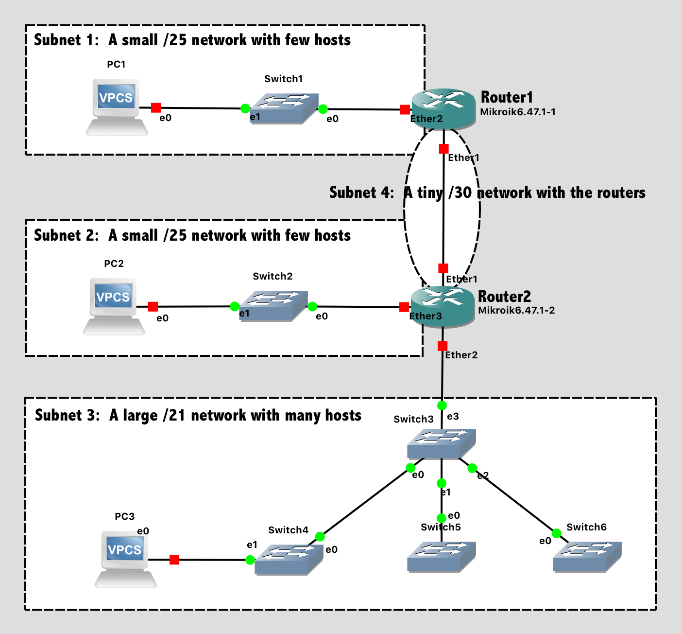
Lab 5 Network Diagram (Note: Subnet labels and dashed borders are for informational use only)
However, BEFORE you even think about opening GNS3, you should first complete the design of the network by filling in the following tables
You are free to choose subnet addresses as you see fit, with the following restrictions:
- All subnets must be in private IP address ranges - It's a very bad practice to overlap with legitimate public IPs
- Subnet 1 must be a
/25network - it's relatively small- Subnet 2 must be a
/25network - it's relatively small- Subnet 3 must be a
/21network - it's much larger- Subnet 4 must be a
/30network - it's tiny and only connects the two routers together- You should follow convention and assign the default gateway IPs to be either the lowest usable host address or highest usable host address in the subnet. (With the exception of subnet 4, where every host is a router)
Tip: There are a variety of subnet calculators available online. As with any calculator, it's important to know how to use it!
Subnets
| Subnet # | Subnet Addressa.b.c.d/n |
Netmask | Number of IPs in Subnet | Lowest Usable Host Address | Highest Usable Host Address |
|---|---|---|---|---|---|
| 1 | |||||
| 2 | |||||
| 3 | |||||
| 4 |
Notes:
- Your Subnet address should have all zero's for the host ID bits. For example, 192.168.10.0/24 (the lower 8 bits are all zero)
- Your Netmask should be in binary in groups of 8. For example,
11111111.11111111.11111111.00000000 - Your Number of IPs in Subnet should include the first and last address (with a host ID of all 0's and all 1's, respectively)
IP Address for all Host Interfaces
| Host | IP Address | Subnet Addressa.b.c.d/n |
|---|---|---|
| PC 1 | ||
| PC 2 | ||
| PC 3 | ||
| Router1, Ether1 Interface | ||
| Router1, Ether2 Interface | ||
| Router2, Ether1 Interface | ||
| Router2, Ether2 Interface | ||
| Router2, Ether3 Interface |
Tips:
- The process goes more smoothly if you configure the routers first, and then the PCs in each subnet.
- The specific port on a switch does not matter (until we get to a point in the semester where we are configuring switches)
- The specific port on a router does matter. The router configuration in software needs to be consistent with the way the cables are wired in hardware.
Configuration Steps:
- Configure the hostnames of the routers in GNS3 to prevent confusion. Use the GUI in GNS3 (right-click, choose "Change Hostname") to change how it looks on the network diagram.
- Configure the hostnames of the routers in the router itself to prevent confusion. Use the
system identity set name=XXXcommand to change the hostname on the router itself. Notice that the command prompt changes to reflect this. You should see[admin@router1] >instead of[admin@MikroTik] > - Configure IP addresses on all router interfaces that are connected to subnets. Use the
ip address add address=a.b.c.d/n interface=XXXcommand. - Configure RIP on the routers. After configuration, verify with
routing rip route printthat the route table is as you desire. - Configure the IP address on each VPC. Use the
ip a.b.c.d/n w.x.y.zcommand. - Save the configuration on the VPCs via the
savecommand and exit safe mode on the router.
Test Network
For testing, ensure that PC1 can successfully ping PC2 and PC3.
Lab Submission
Submit the following items to the Lab 5 Canvas assignment:
The design tables (from above) documenting your subnet design and selected IP addresses.
Provide screenshot(s) showing:
- Your GNS3 topology
- Successful pings from PC1 to PC2
- Successful pings from PC1 to PC3
- The output of
routing rip route printon Router2
When finished, press the Stop button and exit GNS3. The GNS3 VM (in VMware) should halt and exit automatically.