Lab 8 - Firewalls
In this lab, you'll configure a Firewall to restrict network access according to administrative requirements.
Design Network
Your network topology should match this design. There are several subnets being created here:
- "Public Internet" - A subnet representing devices that are external to your organization
- "DMZ" (demilitarized zone) - A subnet containing servers that should be publicly accessible
- "Internal Servers" - A subnet containing servers that should only be accessible from internal devices
- "Internal Workstations" - A subnet containing end-user computers (laptops, workstations, etc.) that should only be accessible from internal devices
Note that the "servers" shown in the network diagram are just more MikroTik routers being repurposed for a new role. GNS3 is certainly capable of running full virtual machines as part of a simulated network, but it's not worth the effort for this lab.
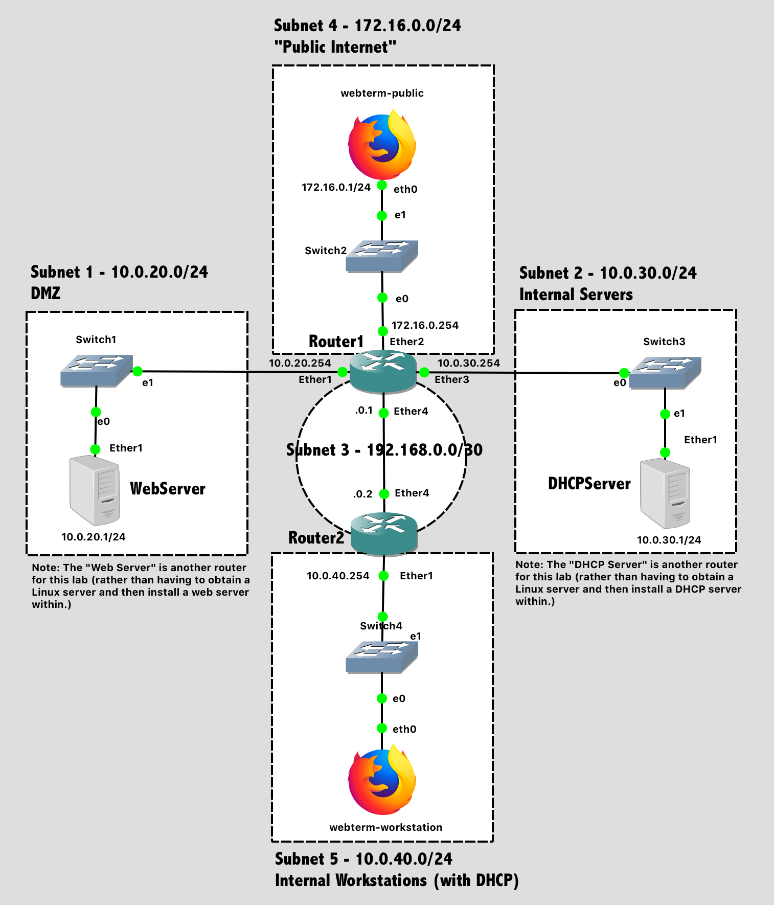
Lab 8 Network Diagram (Note: Subnet labels and dashed borders are for informational use only)
Implementation
Tips:
- The process goes more smoothly if you configure the routers first, and then the PCs in each subnet.
- The specific port on a switch does not matter (unless VLANs are specified)
- The specific port on a router does matter. The router configuration in software needs to be consistent with the way the cables are wired in hardware.
Configuration Steps:
- Configure the hostnames of the routers in GNS3 to prevent confusion (via the GUI).
- Configure the hostnames of the routers in the router itself to prevent confusion (via the CLI).
- Disable the DHCP Client on each router. (Unless you ran Wireshark on a link, you wouldn't have previously noticed that a new MikroTik router defaults to running a DHCP client on Ether1, trying to auto-configure that network port so a new administrator can access the router over the network. It's not helpful for us here.)
ip dhcp-client printfollowed byip dhcp-client remove numbers=0will eliminate this. - Configure IP addresses on all router interfaces that are connected to subnets.
- Configure dynamic routing (RIP) on Router1 and Router2 between subnets 1-5. After configuration, verify with
routing rip route printthat the route table is as you desire.- Don’t be lazy and run RIP on “all” interfaces. Only run RIP on the interfaces between Router1 and Router2.
routing rip interface add interface=etherX send=v2 receive=v2 # For the interface going to other routersrouting rip interface add interface=etherY passive=yes # For the interface going to clients
- Configure a static IP on webterm-public.
- Enable the DHCP client on webterm-workstation.
Fake Servers
MikroTik Router as a Web Server
Rather than create another Linux virtual machine and install a webserver into it, we're just going to use the existing MikroTik router as our example web server for the DMZ. After all, it does have a web interface already running on it.
- Assign the "server" a hostname (
WebServer) - Assign the "server" an IP address
- Assign the "server" a static default route, so it sends all traffic to
Router1. Tip: Look through previous labs for how to create a static route. To make it a default route, the destination address should be0.0.0.0/0(meaning all addresses), and the gateway should be the IP address ofRouter1that is part of the same subnet. Thanks to Longest Prefix Match, destination addresses within the local subnet will still be reachable directly, but all other destinations will go to the default gateway.
Because this device is intended to be a server, not a router, it should not participate in RIP across the network.
You can use the "Change Symbol" menu option if you want your network diagram to show a server symbol instead of a router symbol.
Mikrotik Router as a DHCP Server
Rather than create another Linux virtual machine and install a DHCP server into it, we're just going to use the existing MikroTik router as our example DHCP server for the internal subnet. After all, it does have a DHCP server already installed on it.
- Assign the "server" a hostname (
DHCPServer) - Assign the "server" an IP address
- Assign the "server" a static default route, so it sends all traffic to
Router1
Because this device is intended to be a server, not a router, it should not participate in RIP across the network.
You can use the "Change Symbol" menu option if you want your network diagram to show a server symbol instead of a router symbol.
Dynamic Host Configuration Protocol (DHCP) Relay
In this lab, devices in Subnet 5 should be able to obtain their network configuration via DHCP. However, the DHCP server is not Router2, which is directly connected to the subnet. Instead, the DHCP server is located in Subnet 2. Thus, DHCP relaying is needed.
First, configure Router2 to function as a DHCP relay. When Router2 receives a DHCP request on the specified interface, it will forward it to DHCPServer.
ip dhcp-relay add interface=ether1 dhcp-server=10.0.30.1 name=relay1 disabled=no
ip dhcp-relay print
Second, configure DHCPServer to assign addresses for Subnet 5.
- Create a DHCP pool with a range of IP addresses to give to clients. You'll want to exclude addresses that are used by the router itself or any other statically-configured network devices in that subnet. (
ip pool add ....) - Enable a DHCP server on a specific interface, using a specific pool of IP addresses, and offering IP address "leases" for a specified time period. Set
disabled=noto enable this server. (ip dhcp-server add interface ...). Note that, for this command, you need to add one additional argument compared to the last lab. The relay argument should be added and specify the IP address where these relayed DHCP requests were captured from. In our case,10.0.40.254(the interface ofRouter2that faces Subnet 5). - Configure DHCP to communicate the subnet information, desired DNS servers (8.8.8.8, 8.8.4.4), and default gateway to clients.
Test Network - Before Firewall
For testing:
- Ensure that webterm-workstation has obtained an IP address via DHCP. (Run
ip dhcp-server lease printonDHCPServer) - Ensure that webterm-public can successfully ping the
WebServer,DHCPServer, andwebterm-workstation. - Ensure that webterm-public can load the web page of the WebServer (http://10.0.20.1)
Document these results with screenshots before you add in firewall rules next.
Firewall
Now, you will configure a firewall on Router1 for the network. The firewall operates by means of firewall rules. Each rule consists of two parts - the matcher which matches traffic flow against given conditions and the action which defines what to do with the matched packet, such as allow or deny.
Firewall filtering rules are grouped together in chains. This allows a packet to be matched against one common criterion in one chain, and then passed over for processing against some other common criteria to another chain. There are three predefined chains, which cannot be deleted:
- Input - used to process packets whose destination is the router itself. In other words, packets where the destination IP address is one of the router's addresses. Packets passing through the router are not processed against the rules of the input chain.
- Output - used to process packets that originated from the router and are leaving it through one of the interfaces. Packets passing through the router are not processed against the rules of the output chain.
- Forward - used to process packets passing through the router .
In today’s lab, we will only use the forward chain.
When processing a chain, rules are taken from the chain in the order they are listed from top to bottom. If a packet matches the criteria of the rule, then the specified action is performed on it, and no more rules are processed in that chain. If a packet has not matched any rule within the built-in chain, then it is accepted.
Create firewalls rules on Router1 that perform the following actions:
- Incoming HTTP connections from Subnet 4 to the web server should be allowed:
ip firewall filter add chain=forward action=accept protocol=tcp port=80 connection-state=new src-address=172.16.0.0/24 dst-address=10.0.20.1 comment="Permit Web Server in DMZ" - Packets that are part of established connections (or related) should be allowed. This allows the response from the web server to go back to the requesting client:
ip firewall filter add chain=forward action=accept connection-state=established,related comment="Accept established connections" - Everything else should be denied:
ip firewall filter add chain=forward action=drop comment="Default deny"
View your firewall chain after creation with ip firewall filter print chain=forward. Each firewall rule must be in the order specified above. First you allow specific new connections to pass, then you allow all the establish & related connections to pass, and finally you deny anything else not specifically permitted above.
Test your network
- Can your webterm-public access the webpage on
WebServer? (http://10.0.20.1) Should succeed - explicitly allowed by forward chain - Can your webterm-public access the webpage on
DHCPServer? (http://10.0.30.1) Should fail - covered by default deny on forward chain - Can your webterm-public access the webpage on
Router1? (http://172.16.0.254) Should succeed - input chain is not configured yet (and is default-allow) (You could also access router at IP 10.0.20.254, 10.0.30.254, etc... and all will work, because all of those destination IPs would be processed by the input chain)
Let's add a few rules concerning subnet 2 for internal servers. As it stands right now, the firewall is blocking the DHCP relay!
Create a firewall rule on Router1 that perform the following actions:
- Incoming DHCP requests (UDP Port 67) from Subnet 3 to the DHCPServer should be allowed:
ip firewall filter add chain=forward action=accept protocol=udp port=67 connection-state=new src-address=192.168.0.0/30 dst-address=10.0.30.1 comment="Permit DHCP Relay to Internal Server" - Outgoing DHCP replies from the DHCPServer to Subnet 5 should be allowed:
ip firewall filter add chain=forward action=accept protocol=udp port=67 connection-state=new src-address=10.0.30.1 dst-address=10.0.40.0/24 comment="Permit DHCP Response"
On your webterm-workstation, try to manually re-run the DHCP client now to verify DHCP is working:
/tmp/gns3/bin/udhcpc -v
Sending discover...
Sending discover...
Sending discover...
(CTRL-C to exit)
Hmmmn. Non-functional. View your firewall chain after creation with ip firewall filter print chain=forward. Notice the problem? The firewall rules you just added are after the default deny rule, and thus will never have any effect. Move them earlier in the list, above the established connections and default deny rules: ip firewall filter move numbers=3,4 destination=1
Now try to manually re-run the DHCP client:
/tmp/gns3/bin/udhcpc -v
Sending discover...
Sending select for 10.0.40.253...
Lease of 10.0.40.253 obtained, lease time 86400
Lab Submission
Submit the following items to the Lab 8 Canvas assignment:
- Provide a screenshot showing your GNS3 topology
- Provide a screenshot showing the output of
ip dhcp-server lease printonDHCPServer - Provide a screenshot showing webterm-public successfully loading the the web server (http://10.0.20.1)
- Provide a screenshot showing successful pings from webterm-public to the WebServer, DHCPServer, and webterm-workstation prior to firewall rules being added.
- Provide a screenshot showing the output of
ip firewall filter printonRouter1after adding the HTTP and DHCP rules. - Provide the command: Let's say there was an SMB (Windows file sharing) server located in Subnet 2. What would be the command(s) to add firewall rule(s) to
Router1that allow workstations in Subnet 5 to access it? You only need to allow the "modern" (Windows 2000 and up) port of 445, not legacy ports. - Provide the command: Let's say you want to allow pings (ICMP, in general) between any devices in subnets 1, 2, 3, and 5 (i.e. excluding the "public Internet" subnet), but don't want to allow any other traffic beyond the rules already added above. What would be the command(s) to add firewall rule(s) to
Router1to enable this? (Tip: You could do this with a number of rules. Or you could do this with a single rule and anaddress-list. Consult the MikroTik web documentation or the in-router help system by pressing?at every step of the way while trying to write your command(s). Try pinging before, then enter your rule(s), and verify that pings are now functional.)
When finished, press the Stop button and exit GNS3. The GNS3 VM (in VMware) should halt and exit automatically.