Lab 9 - Network Address Translation
In this lab, you'll connect your virtual GNS3 topology to the Internet and configure Network Address Translation (NAT) on a router.
Design Network
Your network topology should match this design.
Tip: Save yourself some time here because the internal network is the same as Lab 6! Open the Lab 6 project, and then use the “Save As” option in GNS3 to create a new project called Lab 9. Don’t just copy and paste the data file outside of GNS3. Your project depends on resources that exist inside the GNS3 VM, so you need to copy your project within GNS3 to also duplicate those resources.
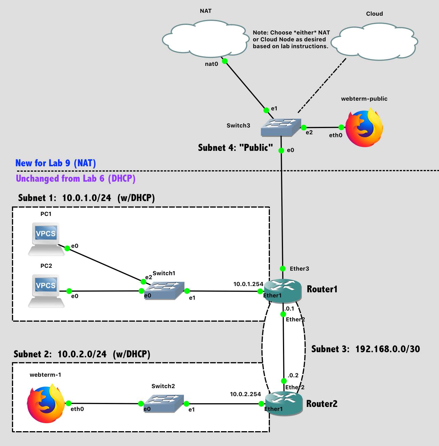
Lab 9 Network Diagram (Note: Subnet labels and dashed borders are for informational use only)
Implementation
Tips:
- The process goes more smoothly if you configure the routers first, and then the PCs in each subnet.
- The specific port on a switch does not matter (unless VLANs are specified)
- The specific port on a router does matter. The router configuration in software needs to be consistent with the way the cables are wired in hardware.
Configuration Steps:
- Configure the hostnames of the routers in GNS3 to prevent confusion (via the GUI).
- Configure the hostnames of the routers in the router itself to prevent confusion (via the CLI).
- Disable the DHCP Client on each router. (Unless you ran Wireshark on a link, you wouldn't have previously noticed that a new MikroTik router defaults to running a DHCP client on Ether1, trying to auto-configure that network port so a new administrator can access the router over the network. It's not helpful for us here.)
ip dhcp-client printfollowed byip dhcp-client remove numbers=0will eliminate this. - Configure IP addresses on all router interfaces that are connected to subnets.
- Configure dynamic routing (RIP) on Router1 and Router2 between subnets 1-3. After configuration, verify with
routing rip route printthat the route table is as you desire.- Don’t be lazy and run RIP on “all” interfaces. Only run RIP on the interfaces between Router1 and Router2.
routing rip interface add interface=etherX send=v2 receive=v2 # For the interface going to other routersrouting rip interface add interface=etherY passive=yes # For the interface going to clients
- Configure DNS for Router1 and Router2 using the Google Public DNS IP addresses.
ip dns set servers=8.8.8.8,8.8.4.4followed byip dns printto confirm your setup. - Enable the DHCP client on the VPCs and both Webterm clients
- Save the configuration on the VPCs via the
savecommand and exit safe mode on the router.
Connecting GNS3 to Internet
The GNS3 network simulator provides two different nodes that allow access to the physical network - the Cloud node, and the NAT node.
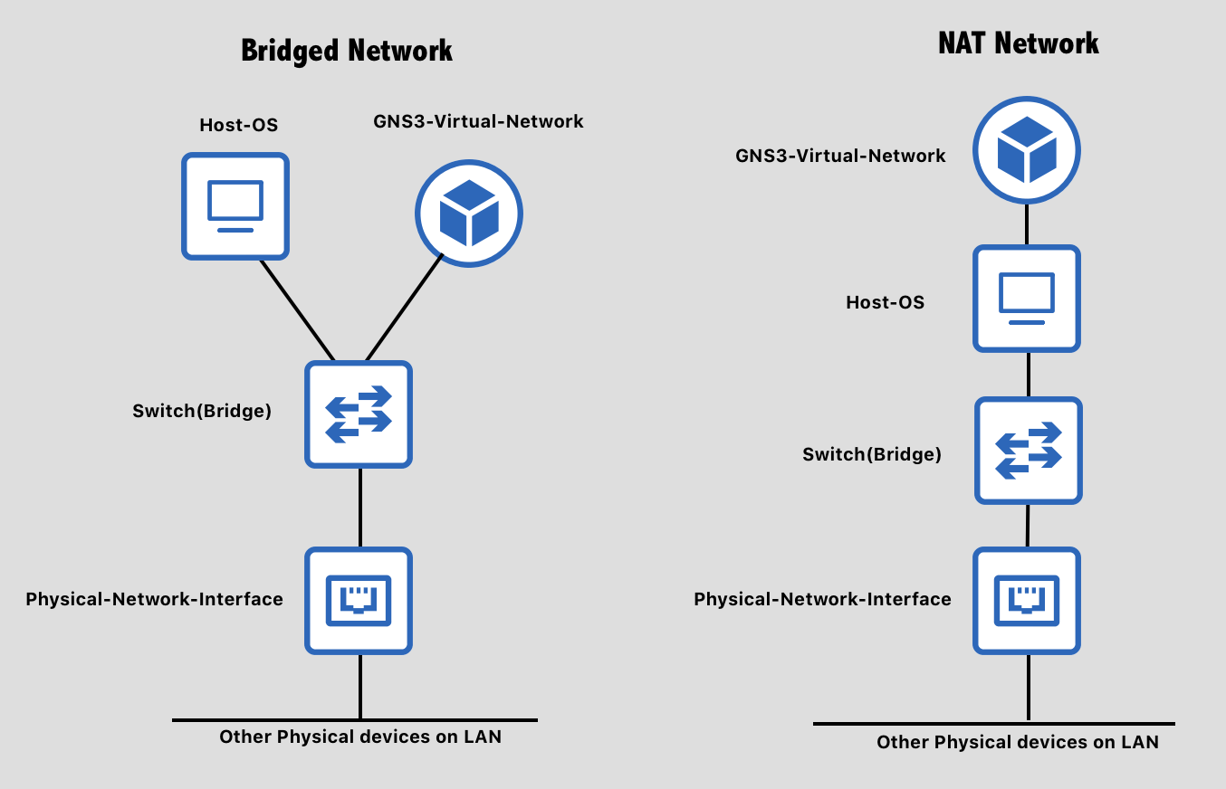
- The Cloud node bridges your GNS3 topology with your physical network, as if both your native OS and your GNS3 network were connected to the same physical switch. This is useful when you want to allow external access into your GNS3 network without any interference. To setup the cloud node, you have to choose the specific physical network interface that you want to bridge with. Network bridging is most successful with wired network adapters (e.g. Ethernet), and less successful with wireless network adaptors. One reason is that the wireless network access point tracks authentication by MAC address, and without some software trickery, a second MAC address appearing on the wireless network won't be authenticated. Thus, you'll "bridge", but anyting you send will be ignored.
- The NAT node also allows your GNS3 topology to access the physical network, but via address translation, so that GNS3 requests appear to be coming from your host OS. This is suitable for downloading files from the Internet (like software updates for virtual appliances), but not for allowing much in the way of external access to your GNS3 network. It is, however, more reliable across a wide variety of system configurations.
Choose the node type that is most likely to work on your system. Either Cloud or NAT is sufficient for this lab. You're welcome to try to get the cloud (bridged) node working first, and fall back to NAT if needed. Drag that node into your network diagram. Note: Unlike every other node used in lab, here you do NOT want to run your Cloud or NAT node in the GNS3 VM, which would then require you to troubleshoot virtual machine networking too. Instead, you want the Cloud or NAT node to run on your host computer.
Run DHCP on the Router1 interface connected to the Cloud/NAT node, so your router can request an IP from this network. First add the DHCP-client service with ip dhcp-client add interface=ether3 disabled=no. Then, check to see if it is running with ip dhcp-client print, and finally verify that the interface address is set with ip address print
Check the Routing table for Router1 with ip route print. What does the router do with a packet that doesn’t match any existing rule? (Look for a default route, 0.0.0.0/0). Router1 will forward it out ether3, towards the Cloud/NAT node.
Check the Routing table for Router2 next. What does the router do with a packet that doesn’t match an existing rule? (Look for a default route, 0.0.0.0/0). Nothing! There is no default route yet.
Configure RIP on Router1 to distribute information about the default route (0.0.0.0/0) to other routers. This is not enabled by default, but can be activated with routing rip set distribute-default=if-installed. This rule is only needed on Router1, which has a default route set via the DHCP client you previously configured on the port connected to the Cloud/NAT.
One last configuration item is required. You have a number of subnets in your GNS3 network that all want Internet access. However, the NAT node in software will only map a single subnet to the host network. The Cloud node has a similar limitation, albeit one that is imposed by your physical network and physical router. Short of changing your physical network to speak RIP with Router1, the easiest way to handle this is to run address translation on Router1 as well, so that all outbound traffic (from many devices) appears to come from Router1 only. This feature - IP "Masquerading", is a standard feature of Linux and is also available in the MikroTik IP firewall. Enable it by: ip firewall nat add chain=srcnat action=masquerade out-interface=ether3. (out-interface is the cloud-facing interface).
Networking Testing
You should be able to ping google.com from everywhere. Try it from webterm-1, Router1, Router2, and PC1.
Lab Submission
Submit the following items to the Lab 9 Canvas assignment:
- Provide a screenshot showing your GNS3 topology
- Provide a screenshot showing the output of
ping google.comonRouter1andRouter2 - Provide a screenshot from
webterm-1showing both the output ofip addrand https://cyberlab.pacific.edu loaded in Firefox. What device on the network assigned the IP address ofwebterm-1? - Provide a screenshot from
webterm-publicshowing both the output ofip addrand https://cyberlab.pacific.edu loaded in Firefox. What device on the network assigned the IP address ofwebterm-public? - Provide two Wireshark .pcapng files. Each of these files should ONLY contain two packets each - a request and a reply from a ping between a VPCS or Webterm-1 (your choice) and 8.8.8.8 (Google). Construct these files VERY carefully!
internal.pcapngshould be the network link "inside"Router1(in the virtual network)external.pcapngshould be the network link "outside"Router1(heading toswitch3and the NAT or Cloud)- Filtering Requirement: Your .pcapng files should contain the same two packets along its path. Filter to ensure that the identifier and sequence number match exactly. This must be the exact same packet. (You can use
icmp.ident==XXXX && icmp.seq==YYYYas an example filter) - Tip: The network link “outside” Router1 will be very busy if you were able to instantiate a Cloud node instead of a NAT node, as GNS3 is sniffing all packets on your computer in order to make this work. It’s no different from running Wireshark on your host OS. So work quickly and STOP CAPTURE as soon as you get a few successful pings.
- Provide a short answer to the question: What exactly has
Router1modified in the outgoing ICMP echo request? (when forwarding from internal to external network) - Provide a short answer to the question: What exactly has
Router1modified in the incoming ICMP echo reply? (when forwarding from external to internal network)
When finished, press the Stop button and exit GNS3. The GNS3 VM (in VMware) should halt and exit automatically.